Working Media based High Velocity Forming
Analogous to conventional hydroforming, in high rate hydroforming the force is applied via a solid, fluid or gaseous working medium and thus, only one die is required, but in contrast to the quasistatic case, Pascal’s principle is no longer valid here. Instead of a homogeneous pressure distribution in the fluid, here a pressure impulse propagates through the fluid as a pressure wave or a shockwave (e.g. [Lan93]). This pressure wave accelerates the workpiece in its propagation direction. According to the initiation mechanisms of the shockwave
- electrohydraulic forming,
- explosive forming and propellant forming, and
- the hydropunch process
- vaporizing foil actuators
can be distinguished.
Characteristics of a shockwave
A shockwave is characterized by
- an expansion velocity that is (slightly) higher than the specific sonic speed of the working medium,
- an extremely fast pressure rise in the range of a few nanoseconds in low energy applications (e.g. in an lithotripter) up to the range of a few microseconds in higher energy applications (i.e. industrial applications as forming or destroying ceramic cores inside castings), and
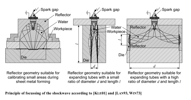
- a spatial form and expansion that depends on and can be influenced via the setup. Reflectors can be used for directing or focusing the shockwave.
However, in an industrial application the forming process is the result of a pressure wave but not of the shockwave. The expansion velocity of the shockwave is typically slightly higher than the specific sonic speed of the working medium but the measured forming velocity is much lower. For example, electrohydraulic forming tests with shockwave generation inside water result in an average forming velocity of 67 m/s. The velocity maximum at the end of the forming process is between 250 and 300 m/s. For comparison, the sonic speed in water is 1,450 m/s. On the other hand, it is possible to form metal plates which are not in contact with the water surface, depending on the used pulse energy and the electrode distance from the water surface. These perceptions explain that the electrohydraulic forming process is a result firstly of the accelerated water in consequence of a water steam bubble generated by the plasma channel and secondly of the inertia of masses of the workpiece.
Explosive forming
The earliest known publication about impulse forming, an English patent, is related to tube joining and tube expansion, respectively, by means of an explosive charge [GB 21840]. The first patent dealing with the explosive forming of sheet metal is [US 939702].
Process principle and variants
During explosive forming the shockwave is initiated by a detonating high explosive. Here, one can differentiate between the contact operation and the standoff operation. In the contact operation, the surface of the workpiece is covered with the explosive and the detonation wave accelerates the workpiece directly. By contrast, in the standoff operation, workpiece and die are positioned in a working medium and the explosive is ignited in some distance to the workpiece initiating a shockwave that travels through the working medium before accelerating the workpiece (e.g. [Neu88]).
In the standoff operation, the peak pressures are typically lower than in case of the contact operation [Bru68]. The reason is that friction, heat conduction and expansion result in fractional dissipation of the detonation energy.
Selected process parameters
According to [Neu88], important parameters for the process design are
- the distance between the mass and the explosive
- the brisance of the explosive, and
- the state of the working medium (gaseous, fluid or granular).
In case of granular working media as e.g. sand and metal or wooden chips, also
- the density of the working medium, and
- the humidity of the working medium are decisive with regard to the efficiency of the energy transfer and, consequently, considering the pressure applied to the workpiece.
Furthermore, the explosive is formed to different shapes according to the application. In the standoff operation for drawing of sheets, spherical shapes are used, while tube bulging is done using twines. Cutting, embossing, and cladding of sheets are usually done in a contact operation using foils or powder. [Lan93].
Propellant forming
Process principle
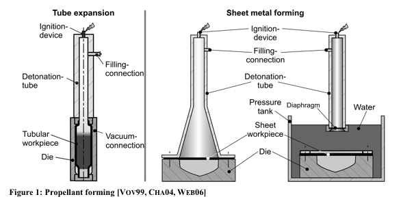
As in explosive forming, in propellant forming, the energy is provided by a detonation but in contrast to the previously described processes, here, a detonating gas mixture is actuator of the process as well as working medium [Web06]. After the ignition, the detonation zone propagates through the detonation tube and the forming process begins when the detonation reaches the workpiece. In comparison to forming with high explosives, the strain rates in propellant forming are significantly lower and the duration of the detonation can take up to some tenths of a second and, thus, is much longer than in case of high explosives [Bru68]. For a reliable process, the concentration and the mixing of the explosive gases as e.g. hydrogen (H2), methane (CH4), propane (C3H8), butane (C4H10) or other hydrocarbons (CnHm) and an oxidant as oxygen (O2) or air as well as the ignition system are decisive [Bru68, Neu90, Vov99].
Electrohydraulic forming
Process principle
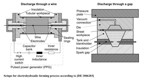
During electrohydraulic forming stored electric energy is suddenly discharged through a spark gap so that the surrounding working medium (e.g. water) is ionized and vaporizes, initiating a shockwave.
Process variants
According to the type of spark gap
- electrohydraulic forming with discharge through a wire (i.e. the electrodes are connected to each other by a wire bridge) and
- electrohydraulic forming with discharge through a gap (i.e. there is no connection between the electrodes) can be differentiated.
According to [Wil64], the setup with a wire bridge is more efficient and can be operated at lower voltages and longer distances between the electrodes, while in case of the setup with discharge through a gap, the process preparation is easier and faster.
The efficiency of an electrohydraulic process can be increased by using a suitable reflector. The reflector design needs to be done taking into account the specific forming task and considering that every redirection of the pressure war is related to energy losses. As shown in [Kle01], the shockwave can be focused by using an elliptic reflector geometry. Spherically spreading from the spark gap, which is positioned in the first focal point of the ellipse, the shockwave is reflected and converges in the second focal point. Other reflector geometries can be used for bulging tubes of different dimensions.
Hydropunch process
The most important high rate mechanical forming operation is the hydropunch process [Rat71, Tom69]. As shown in Figure 2, the principle setup of this technology consists of a compressed air system, accelerating a plunger up to velocities in the range of 30m/s before it dips into the working medium. As aresult of the impact, the fluid is compressed and pressed into the tool unit. The resulting pressure forms the workpiece into the die cavity.
Vaporizing Foil Actuators (VFA)
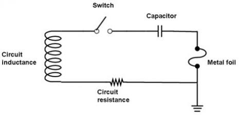
RLC circuit diagram of the VFA setup
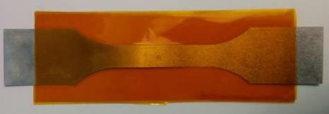
In this technique, electrical energy stored in a capacitor bank is released through a switched circuit (illustrated to the right) that contains a thin metal conductor, such as a wire or foil (pictured below). When the energy deposition rate into the conductor is very high, it can be heated above its energy of sublimation before it has time to melt. This, the conductor vaporizes directly into a gas that expands rapidly. The result is a high-pressure pulse that, when physically constrained, can be harnessed as a tool to drive workpieces. The VFA tool is small, light, and agile, adaptable with little retooling for a wide variety of small-scale impulse-based metalworking applications. More details about his technique can be found at iml.osu.edu.
7″ long aluminum foil actuator; polyimide tape covers the center of the region to electrically insulate the conductor from the VFA assembly
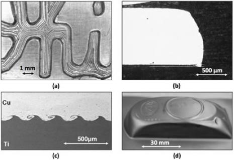
Various applications of the VFA tool: (a) embossing, (b) shearing, (c) collision welding of dissimilar metals, (d) forming

